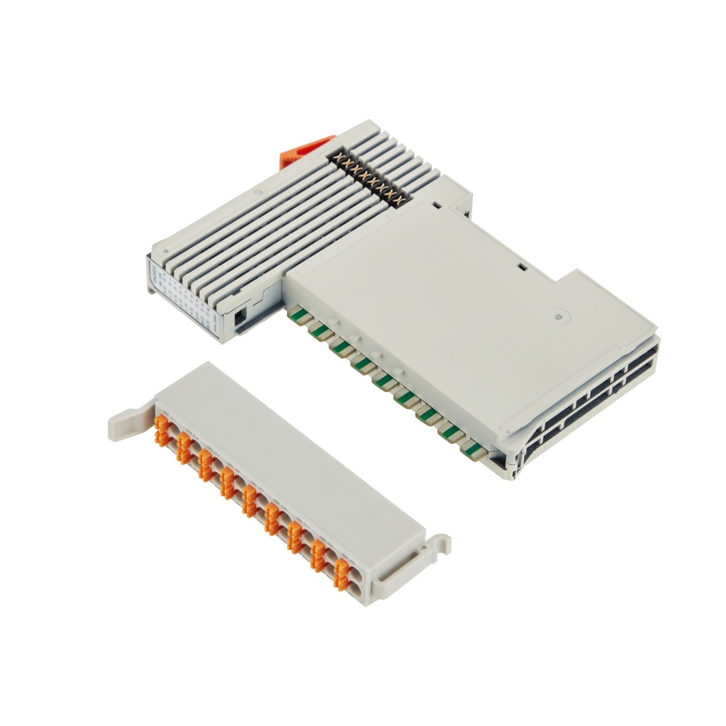
Distributed I/O System 8-Channel Analog Input Module N3087
  • Distributed I/O System 8-Channel NTC Thermistor Input Module N3087,Distributed I/O System 8-Channel Analog Input Module N3087
  • Distributed I/O System 8-Channel NTC Thermistor Input Module N3087,Distributed I/O System 8-Channel Analog Input Module N3087
  • Distributed I/O System 8-Channel NTC Thermistor Input Module N3087,Distributed I/O System 8-Channel Analog Input Module N3087
  • Distributed I/O System 8-Channel NTC Thermistor Input Module N3087,Distributed I/O System 8-Channel Analog Input Module N3087
  • Distributed I/O System 8-Channel NTC Thermistor Input Module N3087,Distributed I/O System 8-Channel Analog Input Module N3087
  • Distributed I/O System 8-Channel NTC Thermistor Input Module N3087,Distributed I/O System 8-Channel Analog Input Module N3087
  • Distributed I/O System 8-Channel NTC Thermistor Input Module N3087,Distributed I/O System 8-Channel Analog Input Module N3087
  • Distributed I/O System 8-Channel NTC Thermistor Input Module N3087,Distributed I/O System 8-Channel Analog Input Module N3087
  • Distributed I/O System 8-Channel NTC Thermistor Input Module N3087,Distributed I/O System 8-Channel Analog Input Module N3087
  • Distributed I/O System 8-Channel NTC Thermistor Input Module N3087,Distributed I/O System 8-Channel Analog Input Module N3087
  • Distributed I/O System 8-Channel NTC Thermistor Input Module N3087,Distributed I/O System 8-Channel Analog Input Module N3087
  • Distributed I/O System 8-Channel NTC Thermistor Input Module N3087,Distributed I/O System 8-Channel Analog Input Module N3087

Distributed I/O System 8-Channel NTC Thermistor Input Module N3087

No.N3087
N3087 is an 8-channel NTC thermistor input module for 2-wire NTC sensors. It offers a measurement range of 184.8–667,828 Ω, 16-bit resolution, a 300 ms conversion rate, and ±2% accuracy using a 100 kΩ resistor within a 20 m AWG16 shielded cable. Each input channel is electrically isolated and requires a suitable coupler such as the BL210 series.
Description
N Series Distributed I/O

Sense. Isolate.
Measure.

N3087 provides 8 NTC thermistor input channels, NTC1 through NTC8. It connects 2-wire NTC thermistor sensors (R25 = 10 kΩ, B25/85 = 3976 K) for on-site temperature acquisition.

Each channel input is electrically isolated and converted into a digital signal transmitted at 16-bit resolution, with a 300 ms conversion rate and a measurement range of 184.8 Ω to 667,828 Ω.

8NTC input channels
16 BitSignal resolution
±2%Accuracy with 100 kΩ / 20 m AWG16
300 msConversion rate
N3087 8-channel NTC thermistor input module
8 NTC channelsNTC1 through NTC8.
2-wire NTC 10 kΩR25 = 10 kΩ, B25/85 = 3976 K.
DIN-35 mountFor distributed fieldbus I/O systems.
Technical specifications

N3087 technical specifications.

Input type, measurement range, resolution, accuracy, conversion rate, wiring requirements, environmental ratings, dimensions, terminal definitions, and distributed I/O system requirements.

8NTC input channels
16 BitSignal resolution
±2%Accuracy with 100 kΩ / 20 m AWG16
DIN-35Industrial rail installation

N3087 measurement views

N3087 reads a 2-wire NTC thermistor input (R25 = 10 kΩ, B25/85 = 3976 K) and reports it as a temperature or as a resistance value on the same 8-channel, electrically isolated, 16-bit input platform.

Shared 8-channel NTC input platform
Selection point Temperature view Resistance view
Model N3087 N3087
Measured quantity Temperature (°C) Resistance (Ω)
Range -50°C to 150°C (see R-T table) 184.8 Ω to 667,828 Ω
Channels 8 channels 8 channels
Resolution 16 Bit 16 Bit
Conversion rate 300 ms 300 ms

Electrical specifications

NTC input, conversion, power, and indication data for the N3087 module.

01
ModelN3087
Input channels8 channels, NTC1 to NTC8
Input type2-wire NTC thermistor, R25 = 10 kΩ, B25/85 = 3976 K (reference value)
Measurement range184.8~667,828 Ω
Channel isolationEach channel input is electrically isolated and converted into a digital signal
Resolution16 Bit
Accuracy±2% with a 100 kΩ resistor, within a 20 m AWG16 shielded cable
Conversion rate300 ms
Internal bus power5 VDC, 31 mA at 5 VDC
Power indicationLeft P: 24 V power indicator; right P: 3.3 V power indicator; red LED on means power normal, off means power abnormal
Channel indicationPanel positions 1 to 16 are reserved
Panel markingI/O module signal type and I/O module model are printed on the panel

8-channel NTC input

The module provides NTC1 through NTC8 and connects 2-wire NTC thermistor sensors with R25 = 10 kΩ and B25/85 = 3976 K.

Electrically isolated inputs

Each channel input is electrically isolated and converted into a digital signal transmitted at 16-bit resolution.

Distributed I/O module

N3087 is an optional N-Series I/O module and must be combined with a suitable coupler, such as a BL210 Series coupler.

N3087 NTC input characteristics

8 NTC inputs. 16-bit. 300 ms.

N3087 combines eight electrically isolated NTC thermistor input channels, 2-wire NTC 10 kΩ sensor support, 16-bit resolution, ±2% accuracy, a 300 ms conversion rate, cage spring wiring, and stated EMC protection.

🌡

8-channel input

Read NTC1 through NTC8 in one 15.4 mm-wide module.

⚙️

Two-wire NTC 10 kΩ

Connect 2-wire NTC thermistor sensors with R25 = 10 kΩ and B25/85 = 3976 K.

📦

16-bit input

Input signals are converted into digital values with 16-bit resolution and a 300 ms conversion rate.

🛡️

Specified environment

IP20 protection, IEC 61000-4-2 and IEC 61000-4-5 Level 3 EMC, and -20°C to 55°C operation.

Reference data

NTC temperature–resistance table.

Reference values for the 2-wire NTC thermistor (R25 = 10 kΩ, B25/85 = 3976 K) used with the N3087 module. Resistance values are in ohms.

Temperature ↔ resistance reference

Values taken from the N3087 user manual, V1.0.

2-wire NTC · 10K3A1
°C Ω °C Ω °C Ω °C Ω
-50 667,828 8 21,921 23 10,923 70 1,751
-40 335,671 9 20,885 24 10,450 75 1,480
-30 176,683 10 19,904 25 10,000 80 1,256
-20 96,974 11 18,974 26 9,572 85 1,070
-15 72,895 12 18,092 27 9,165 90 916.1
-10 55,298 13 17,257 28 8,779 95 787
-5 42,314 14 16,465 29 8,408 100 678.6
0 32,650 15 15,714 30 8,056 105 587.3
1 31,030 16 15,001 35 6,530 110 510.1
2 29,500 17 14,325 40 5,325 115 444.5
3 28,054 18 13,623 45 4,367 120 388.6
4 26,688 19 13,053 50 3,601 125 340.8
5 25,396 20 12,494 55 2,985 130 300
6 24,173 21 11,943 60 2,487 140 234.1
7 23,016 22 11,420 65 2,082 150 184.8
Connection and installation

Terminal definitions and module installation.

Use the defined NTC and PE terminals, and install the module on a compliant DIN-35 rail as part of the distributed I/O station.

Terminal definitions

NTC1 to NTC4A1/A2/A3/A4 are NTC1+/NTC2+/NTC3+/NTC4+; B1/B2/B3/B4 are NTC1-/NTC2-/NTC3-/NTC4-.
NTC5 to NTC8A5/A6/A7/A8 are NTC5+/NTC6+/NTC7+/NTC8+; B5/B6/B7/B8 are NTC5-/NTC6-/NTC7-/NTC8-.
Input type2-wire NTC thermistor, R25 = 10 kΩ, B25/85 = 3976 K (reference value).
Protective earthA9 and B9 are PE (shield ground).

Installation and internal bus

Rail and sequenceMount on a DIN 35 rail compliant with IEC 60715 and assemble modules from the fieldbus coupler left to right.
Insert the moduleAlign the spring clips with the grooves on the coupler or previous module, keep the rail clip unlocked, press the module into position until it snaps onto the rail, then lock the rail clip.
Data contactsEight gold-plated, self-cleaning data contacts provide communication and system power through the internal bus.
End cap and removalInstall an end cap on the last module. To remove a module, pry the rail clip upward with a flat-head screwdriver or similar tool and pull the module away from the DIN rail.
Use 0.3 to 2.5 mm² / AWG 22 to 14 conductors, strip 8 to 9 mm / 0.33 in, and use shielded cables as recommended.
N-Series module family

More N-Series I/O module options.

The N-Series includes digital input, digital output, analog input, analog output, RTD, NTC, temperature, pulse, and power modules.

I/O modules can be arranged in different combinations within the distributed I/O station without grouping them by module type.

27 modules · 9 categories

6 modules

DI

+

Digital input options for NPN, PNP, and dry-contact sensing.

  • N116116CH DI Module (Low-Level Trigger / NPN)
  • N116216CH DI Module (High-Level Trigger / PNP)
  • N116316CH DI Module (Dry Contact)
  • N132132CH DI Module (NPN)
  • N132232CH DI Module (PNP)
  • N132332CH DI Module (Dry Contact)

5 modules

DO

+

Digital and relay output options for discrete control.

  • N20848CH Relay Output Module
  • N216116CH DO Module (PNP)
  • N216216CH DO Module (NPN)
  • N232132CH DO Module (PNP)
  • N232232CH DO Module (NPN)

3 modules

AI

+

Analog input options for current and voltage acquisition.

  • N30464CH 16-bit AI Module, Differential Input, ±5V / ±10V
  • N30818CH 16-bit AI Module, Single-Ended Input, 0/4-20mA
  • N30838CH 16-bit AI Module, Single-Ended Input, 0-5V / 0-10V

2 modules

AO

+

Analog output options for current and voltage control.

  • N40818CH 16-bit AO Module, 0/4-20mA Output
  • N40868CH 16-bit AO Module, ±5V / ±10V Output
🌡

4 modules

RTD

+

RTD modules for PT100 and PT1000 temperature sensing.

  • N50414CH RTD Module, three-wire PT100
  • N50424CH RTD Module, three-wire PT1000
  • N50434CH RTD Module, four-wire PT100
  • N50444CH RTD Module, four-wire PT1000
🔵

2 modules

NTC

+

NTC thermistor input options for temperature measurement.

  • N50858CH NTC Module

1 module

Temperature

+

Dedicated thermocouple module for TC signals.

  • N50888CH TC Module

3 modules

Pulse

+

Pulse counting and pulse-output control modules.

  • N90813CH Pulse Counter + 5×DI
  • N90826CH Pulse Output + 2×DO
  • N90832CH Pulse Output (Pulse Count Control) + 4×DI + 2×DO

1 module

Power

+

Additional power support for larger N-Series stations.

  • N7021Power Module
💡
Important system note

When the number of selected N-Series I/O boards exceeds 20, an additional power module is required. If the number is less than 20, no extra power module is needed.

Installation and wiring

Key operating steps from the N3087 manual.

The manual specifies the installation sequence, module insertion and removal procedure, cable selection rules, and the N3087 wiring example.

Installation sequence

Mount the coupler and I/O modules on a DIN 35 rail compliant with IEC 60715, then assemble modules from the fieldbus coupler left to right.

Inserting a module

Align the spring clips with the grooves of the coupler or previous module, keep the rail clip unlocked, press the module into position until it snaps onto the rail, and lock the rail clip.

Removing a module

Use a flat-head screwdriver or similar tool to pry the rail clip upward, then pull the I/O module away from the DIN rail.

Cable selection

Cage spring connections accept solid, stranded, and fine-stranded conductors. Use one conductor per cage spring, 0.3 to 2.5 mm² / AWG 22 to 14, with an 8 to 9 mm strip length.

  • Distributed I/O System 8-Channel NTC Thermistor Input Module N3087,Distributed I/O System 8-Channel Analog Input Module N3087
  • Distributed I/O System 8-Channel NTC Thermistor Input Module N3087,Distributed I/O System 8-Channel Analog Input Module N3087
  • Distributed I/O System 8-Channel NTC Thermistor Input Module N3087,Distributed I/O System 8-Channel Analog Input Module N3087
  • Distributed I/O System 8-Channel NTC Thermistor Input Module N3087,Distributed I/O System 8-Channel Analog Input Module N3087
  • Distributed I/O System 8-Channel NTC Thermistor Input Module N3087,Distributed I/O System 8-Channel Analog Input Module N3087
  • Distributed I/O System 8-Channel NTC Thermistor Input Module N3087,Distributed I/O System 8-Channel Analog Input Module N3087

Want to get more information?

REQUEST A QUOTE
IIoT Gateway Manufacturer

CONTACT US

If you have any queries, get in touch today! Don't hesitate. We try to take the extra step for our customer satisfaction.
FirstName *
LastName *
Email *
Message *
Code *
Verification Code
Leave a message
FirstName *
LastName *
Email *
Message *
Code *
Verification Code
We use Cookie to improve your online experience. By continuing browsing this website, we assume you agree our use of Cookie.